
Always Watching - Raspberry Pi Face Tracker (Part 1)
This is part one of a two-part series of posts which are an experiment in bringing machine intelligence into the realm of DIY hardware. I use a Raspberry Pi, some easily available peripherals, and some Python code to build a robot that is capable of following a face around a room and sending personalised messages to specific individuals. The robot also has the capacity to discover new inviduals on-the-fly with real time training.
I've been wanting to do a project that involved the Raspberry Pi or a similar Arduino but haven't found one compelling enough to invest the money or time. Many of the projects I see online are smart mirrors or PiHoles and neither seem particularly interesting for me. I then came across this post where the author was able to combine Deep Learning with Raspberry Pi technology and I thought it was a great project. After identifying some improvements to this project aswell as some ideas about where I could take it next, I began to source the necessary components.

Title's namesake
The Build
This is the list of components that are necessary for the core setup along with some links and what they are used for:
- Raspberry Pi 4
- I chose the 4GB model so that there is sufficient capacity to load and run simple ML models. I would advise against Raspberry Pi 3 or the Raspberry Pi Zero for any ML applications due to their limited memory sizes.
- Pi Camera
- Is the official Raspberry Pi compatible image capture mechanism.
- Pan Tilt Hat
- This is an addition that allows you to control the angle of the camera. It consists of a two servos (to control movement), a plastic fixture (to house attach the servos and camera), a PCB (manages connections between servos, camera and the Raspberry Pi), and a light diffuser for a separely purchased LED strip.
- Micro SD Card
- The SD card acts the hard drive for the RPI and stores the OS. I went for a 32GB option so there is enough space to store models and temporary images. I also picked a card that has the New Out Of Box software (Noobs) installed for easier setup and since it was cheaper. If you already have an SD card, it is simple to create a bootable disk.
- Power Supply
- This channels power to the computer and some small peripherals through USB-C input.
- Jumper Cables
- The cables allow you to connect different electrical components together. I only needed about 3 cables for the project but I will use more in later projects.
- Keyboard and Mouse
- Basic user input to talk to the Pi.
The following parts are optional or depend on your existing setup:
- Raspberry Pi Case
- This gives a nice housing to the Pi so I'm not overly concerned about damaging the motherboard and also looks quite nice.
- 30cm Flex Cable
- The camera module comes with it's own camera flex cable but it's too short for the full range of movement that the Pan Tilt hat provides.
- Adafruit NeoPixel
- These are a set of programmable LEDs on a PCB that connect to the Pan Tilt hat. Note that these header pins soldered onto the board to connect to the hat.
- Header Pins
- These allow you to connect jumpers from the Pan Tilt hat to the LED strip
- USB-C Switch
- This switch lets me turn on and turn off the Pi without needing to (un)plug the Pi.
- Standoffs
- These are some screws that let you physically mount peripherals to the Pi. In this case I use it to attach the Pan Tilt hat and stop it falling off when the servos jerk.
- Micro-HDMI Adaptor
- Connect a normal size HDMI to the Pi.

The Whole Kit

The Whole Kit Unboxed
Connecting all the parts is fairly straightforward, and apart from handling the delicate case, nothing can really go wrong. One thing I would say is that to connect the light strip to the Pi, header pins need to be soldered onto the board and for a complete beginner, this is a difficult task due to the small and tightly packed contact pads. Once everything was built, the pi definately had some strong Wall-E / Pixar Lamp vibes.
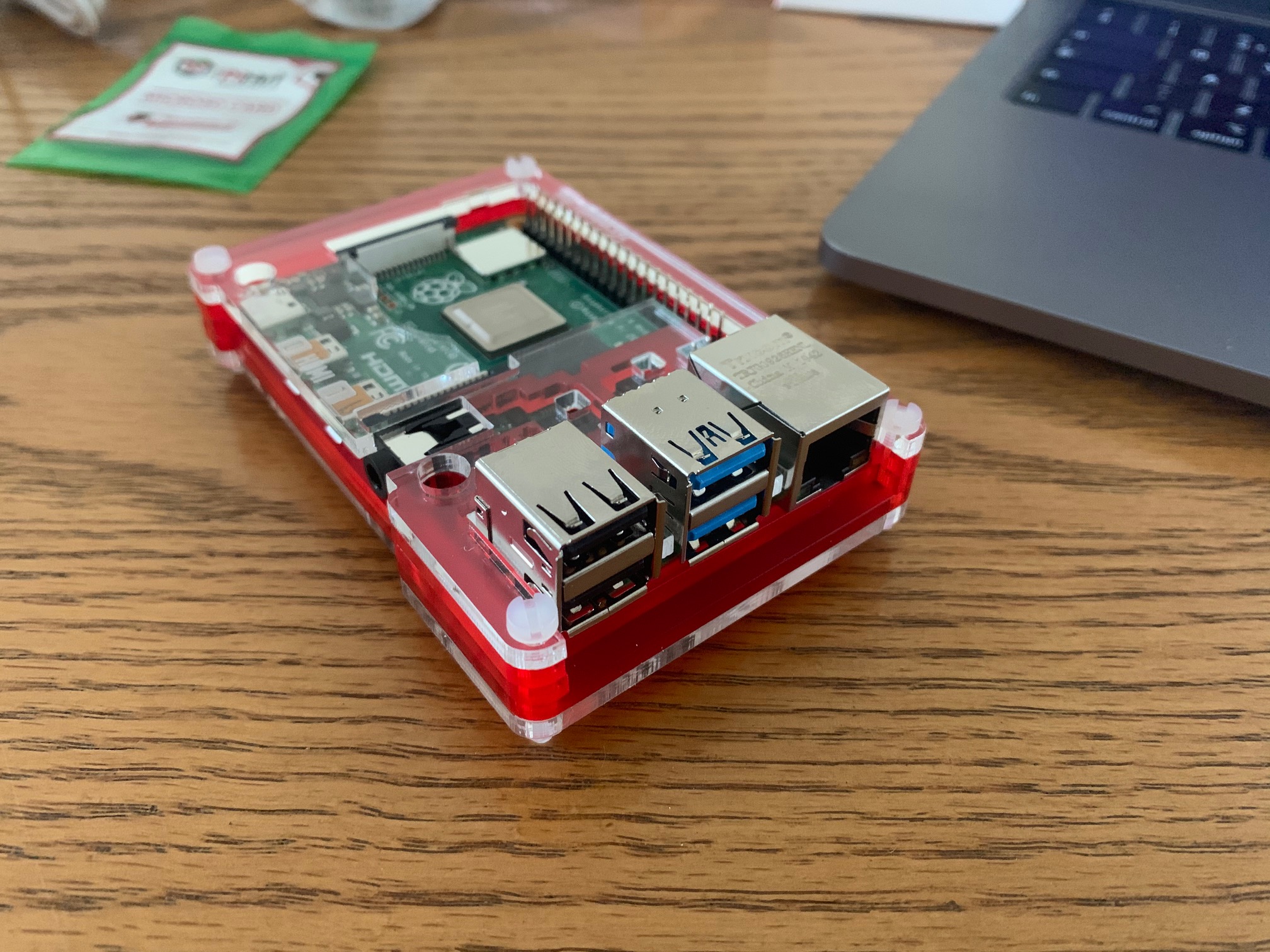
Assembled Raspberry Pi

Pi with Camera Module
Setting Up The Pi
The next step is powering up, establishing how best to interface with the Pi, and testing the components.
Installing an OS
Since I bought an SD card with software already installed, shortly after booting I was greeted with the OS installation wizard. Following the wizard results in a fresh install of Raspbian, a Raspberry Pi friendly Linux derivative.
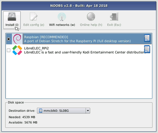
Noobs Install Wizard (source)
Interfacing - SSH
I'm too lazy to not use my primary laptop to control the Pi so I enable SSH through the command line with
sudo raspi-config
This loads the configuration screen where you should go to Interfacing Options > SSH > Yes.

Main Configuration Screen

Interacing Submenu
Then you can find the local IP of the Pi by typing into the command line
hostname -l
And on your main laptop you can SSH into the Pi with
ssh pi@LOCAL_RASPBERRY_PI_IP
Interfacing - Remote Desktop
Since I will also need to see the camera feed from the Pi, I enable the ability to remote desktop into the Pi by going into the config menu as above and enabling Interfacing Options > VNC > Yes. Then, on my Mac, I downloaded VNCViewer and you log in to the Pi with it's local IP and control it like a normal computer.
Interfacing - Data Transfer
The theme of wanting to use my main machine as much as possible continues when I begin writing the software. When starting the project, I create an Git repo on my main machine and code as normal. When it comes to deploying this code onto the Pi, there are two solutions I use:
-
When all code changes made are all made on my laptop, I use the
rsynccommand to copy all files and folders apart from the virtual environment onto the pi with a command similar torsync -r face_tracker pi@192.168.0.55:Desktop/ --exclude=venv. - Sometimes, for the sake of speed, I will edit code straight from the Pi in which case I'll use Git as normal to synchronise code between the laptop and Pi.
Testing The Hardware
By this time it's clear that the networking chip works, USB ports work, the SD card is in working order and the
device powers nicely. The key things remaining to test are the servos, camera, and Neopixel strip.
There are two Python libraries that are useful, pantilthat, the official module of the Pan Tilt
Hat, and picamera
to control the camera. Note that before using the camera, you need to enable the camera function in the config
options as above by selecting Interfacing Options > Camera > Yes.
There are few Python scripts that come with these libraries that lets you test functionality, but it's fairly
straightward to understand the few functions to control the hardware. One thing to note is that I had to manually
adjust the servoX_min and servoX_max attributes from the default values to avoid the motor jamming and quickly wearing
the components out.
    from pantilthat import PanTilt
    import math
    def test_motion():
        """
        Test full range of motion as aswell as lights
        """
        # start in the middle
        # u shape to the top right
        # straght down
        # figure of eithe back to middle

        aimer = PanTilt(
            servo1_min=745,
            servo1_max=2200,
            servo2_min=580,
            servo2_max=1910
        )
        aimer.pan(0)
        aimer.tilt(0)
        time.sleep(1)

        for t in range(0, 90):
            x = t
            y = math.sin(math.radians(t)) * 90
            aimer.pan(x)
            aimer.tilt(y)
            time.sleep(0.01)

        for t in range(90, -90, -1):
            x = 90
            y = t
            aimer.pan(x)
            aimer.tilt(y)
            time.sleep(0.01)

        for t in range(-90, 90):
            x = -t
            y = math.sin(math.radians(t)) * 90
            aimer.pan(x)
            aimer.tilt(y)
            time.sleep(0.01)

        for t in range(90, -90, -1):
            x = -90
            y = t
            aimer.pan(x)
            aimer.tilt(y)
            time.sleep(0.01)

        for t in range(-90, 0):
            x = t
            y = t
            aimer.pan(x)
            aimer.tilt(y)
            time.sleep(0.01)
    import pantilthat
    def test_lights():
        pantilthat.light_mode(pantilthat.WS2812)
        pantilthat.light_type(pantilthat.GRBW)

        r, g, b, w = 0, 0, 0, 0

        try:
            while True:
                pantilthat.set_all(0, 0, 0, 0)
                pantilthat.show()
                time.sleep(0.5)
                pantilthat.set_all(100, 0, 0, 0)
                pantilthat.show()
                time.sleep(0.5)
                pantilthat.set_all(0, 100, 0, 0)
                pantilthat.show()
                time.sleep(0.5)
                pantilthat.set_all(0, 0, 100, 0)
                pantilthat.show()
                time.sleep(0.5)
                pantilthat.set_all(100, 100, 0, 0)
                pantilthat.show()
                time.sleep(0.5)
                pantilthat.set_all(0, 100, 100, 0)
                pantilthat.show()
                time.sleep(0.5)
                pantilthat.set_all(100, 0, 100, 0)
                pantilthat.show()
                time.sleep(0.5)
                pantilthat.set_all(100, 100, 100, 0)
                time.sleep(0.5)
                pantilthat.show()
        except KeyboardInterrupt:
            pantilthat.clear()
            pantilthat.show()
Lights Work
Movements Are Good
Aiming the Robot
The first task on the software part of this project is to be able to make the Pi identify a face in an image frame and be able to point to it.
This task breaks down into four key components:
- Detecting the centre point of a face in a frame
- Calculating the vector of movement for the camera to know how point to face
- Adjusting the servo motors with the movement vector to point at the face
- Enabling all of the above to occur simultaneously
1. Detecting Faces
Face detection is a well-studied task, and the first line of attack for this vision task would normally be a deep learning implementation. However, when working with a low powered computer like the Pi we are heavily constrained by the resources available, and with deep models being computationally expensive especially for a real time task, I decided to start with a less accurate approach.
    import cv2

    ## load model
    # haar_path = path to model file downloaded from https://github.com/opencv/opencv/blob/master/data/haarcascades/haarcascade_frontalcatface.xml
    self.detector = cv2.CascadeClassifier(haar_path)

    ## make inference
    objects = self.detector.detectMultiScale(
        image,
        flags=cv2.CASCADE_SCALE_IMAGE,
    )
I decide to use the method described in a previous article of mine, namely using the OpenCV module's HaarCascadeClassifier model; this needs fewer resources and is still accurate enough for my purpose.
A problem I faced, however, was that model sometimes identified a face when one did not exist, and this would cause many problems when adjusting the servos. I fixed this problem by extracting only the most likely face using confidence intervals.
    objects = self.detector.detectMultiScale3(
        image,
        scaleFactor=1.05,
        minNeighbors=9,
        minSize=(30, 30),
        flags=cv2.CASCADE_SCALE_IMAGE,
        outputRejectLevels=True
    )
If we wrap this code in a while loop that feeds the camera input into this function, we can return the
relative location of a face as a two-dimensional vector. This can then be used to point the camera.
2. Calculating the Vector of Movement
Now that we know the relative location of a face in a frame, we need to figure out how to point to it. This is done using a Proportional-Integral-Derivative (PID) controller. , which is a control feedback loop. A control feedback loop is a mechanism where a system takes continuous measurements of some physical object and makes continuous adjustments to keep a measured variable within some set of values. Here, the measure variable is the error between where the camera is pointing and where it should be pointing. Reducing this error means we would be aiming towards a face by adjusting the servos on our camera module.
Functionally, a PID calculator will take in as an input a history of errors, in our task this is the current position of the camera and the position of the face along a single axis. It will then return a single number representing the magnitude of some mechanical process that needs to made to correct this present error. The output is determined by three aspects:
- Proportional: if the current error is large, the correction to be made will be large. Our case: if we are far away from the face, we should move the servo a proportionally large amount.
- Integral: sums the historical error and forces the system to a steady-state of no error.
- Derivative: a measure of the future value, used to dampen movement by responding to rapid changes in the error quickly
The formula for a PID calculation is:
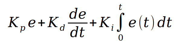
PID Formula
Where kP kI, kD represent constants that should be set for the application. The goal of setting these constants is to ensure the system is responding in the way you want; i.e. it is quick to react, there is no oscillation, and it reacts changes well enough. When choosing these values myself, I spent significant time tuning these to eventually achieve the smoothest movement for my robot. The recommended method of tuning is:
- Set kI, kD to 0.
- Increase kP until the output (camera), then set kP to half this value.
- Increase kI until the oscillation is quickly rectified. Note that too high kI will cause instability.
- Increase kD so that when load is disturbed (face moves in a camera), the system can quickly rectify this.

Example Error Term Chart for Pan Process
3. Adjusting the Servos
Thankfully this part is simpler. The Python module pantilthat has a pan and
tilt methods that take in an angle and adjust the servos.
Code snippets can be seen from the build part of this post.
4. Multiprocessing
The above steps have been described sequentially, but they should be executed simultaneously. To make this happen, we
can use the multiprocessing Python module, to initialise several Python processes that execute
different commands at the same time. Since the different process will need to talk to each other, namely to hand
each other variables that relate to the location of the face, and the result of the two PID functions, we need to
use the process manager. The code for wrapping up these steps is:
	pi_face_detector = PiFaceDetector(rpi=False)

	with Manager() as manager:
		print('Start Manager')

		# set integer values for the object's (x, y)-coordinates
		obj_coord_X = manager.Value("i", pi_face_detector.frame_center_X)
		obj_coord_Y = manager.Value("i", pi_face_detector.frame_center_Y)

		# pan and tilt values will be managed by independed PIDs
		pan_angle = manager.Value("i", 0)
        tilt_angle = manager.Value("i", 0)

		# initialise tuning data variable holder to draw graphs
		tuning_time_data = manager.list()
		tuning_error_data = manager.list()
		tuning_angle_data = manager.list()

        print('Define process')
        # begin recording
		process_start_camera = Process(target=pi_face_detector.start_camera,
			args=(obj_coord_X, obj_coord_Y))

        # calculate PID outputs
		process_panning = Process(target=pi_face_detector.pan_pid_process,
			args=(pan_angle, obj_coord_X, tuning_time_data, tuning_error_data, tuning_angle_data))

		process_tilting = Process(target=pi_face_detector.tilt_pid_process,
			args=(tilt_angle, obj_coord_Y, tuning_time_data, tuning_error_data, tuning_angle_data))

        # move camera
		process_set_servos = Process(target=pi_face_detector.set_servos, args=(pan_angle, tilt_angle))

		# store graph data
		process_save_pan_tuning_process = Process(target=pi_face_detector.save_pan_tuning_process,
			args=(tuning_time_data, tuning_error_data, tuning_angle_data))

		process_save_tilt_tuning_process = Process(target=pi_face_detector.save_tilt_tuning_process,
			args=(tuning_time_data, tuning_error_data, tuning_angle_data))


		print('Start process.')
		process_start_camera.start()
		process_panning.start()
		process_tilting.start()
		process_set_servos.start()
		process_save_pan_tuning_process.start()
		process_save_tilt_tuning_process.start()

		print('Join process.')
		process_start_camera.join()
		process_panning.join()
		process_tilting.join()
		process_set_servos.join()
		process_save_pan_tuning_process.join()
		process_save_tilt_tuning_process.join()
This is a recording of the Pi with all of the above in action. The movement could do with a bit of tuning but it's a great feeling to have achieved this so far.
Tracking
The code can be accessed from my Github. Part two will focus on having the Pi recognise certain faces, respond to these faces in unique ways, and learn new faces on the fly. Stay tuned!